«hot ROM»: welcome to the machine
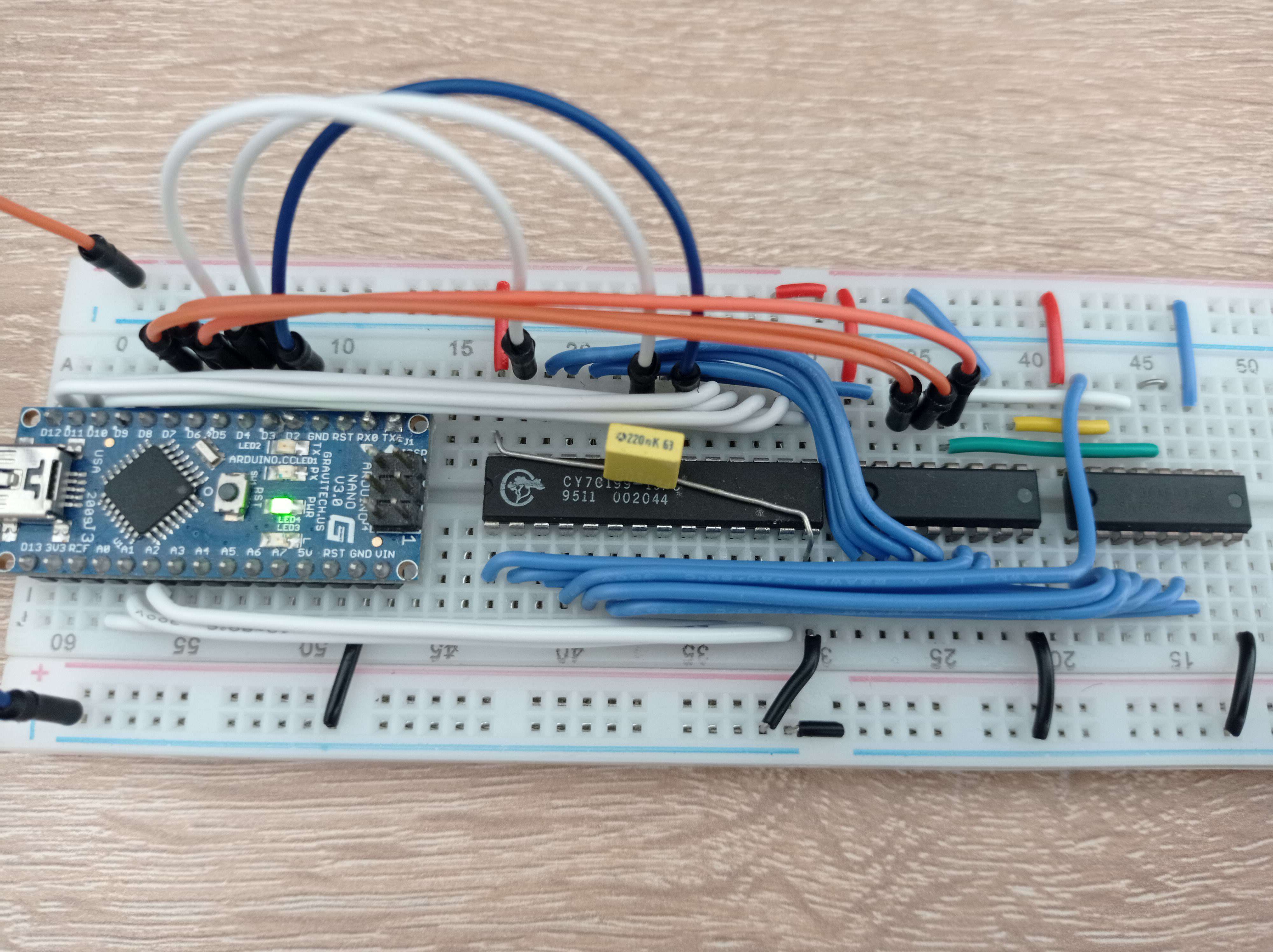
In my previous post, I presented you with a breadboard I populated to prototype the «hot ROM», an extension to the VG-5000µ that would enable its owner to stuff data in the ROM location and boot on it.
Ideally, the hot ROM extension working principle is:
- the extension holds the Reset_ signal.
- the VG-5000µ’s CPU is doing nothing and releases the buses (they go in the so-called high-impedance state).
- a PC (or anything convenient for that purpose) sends commands to the extension through a serial port. Those commands can read/write the content of a static RAM chip.
- the extension is instructed to start the VG-5000µ
- it releases all the buses and signals
- disables the internal ROM chip
- releases the Reset_ signal
- the VG-5000µ boots the content of the RAM chip.
First prototype lessons
The breadboard prototype had a few shortcomings:
- it was not connected to the real machine, and all the ideas I had to plug this board to the extension port did not appear very reliable.
- the memory sometimes did not read as it was written and I could not explain why.
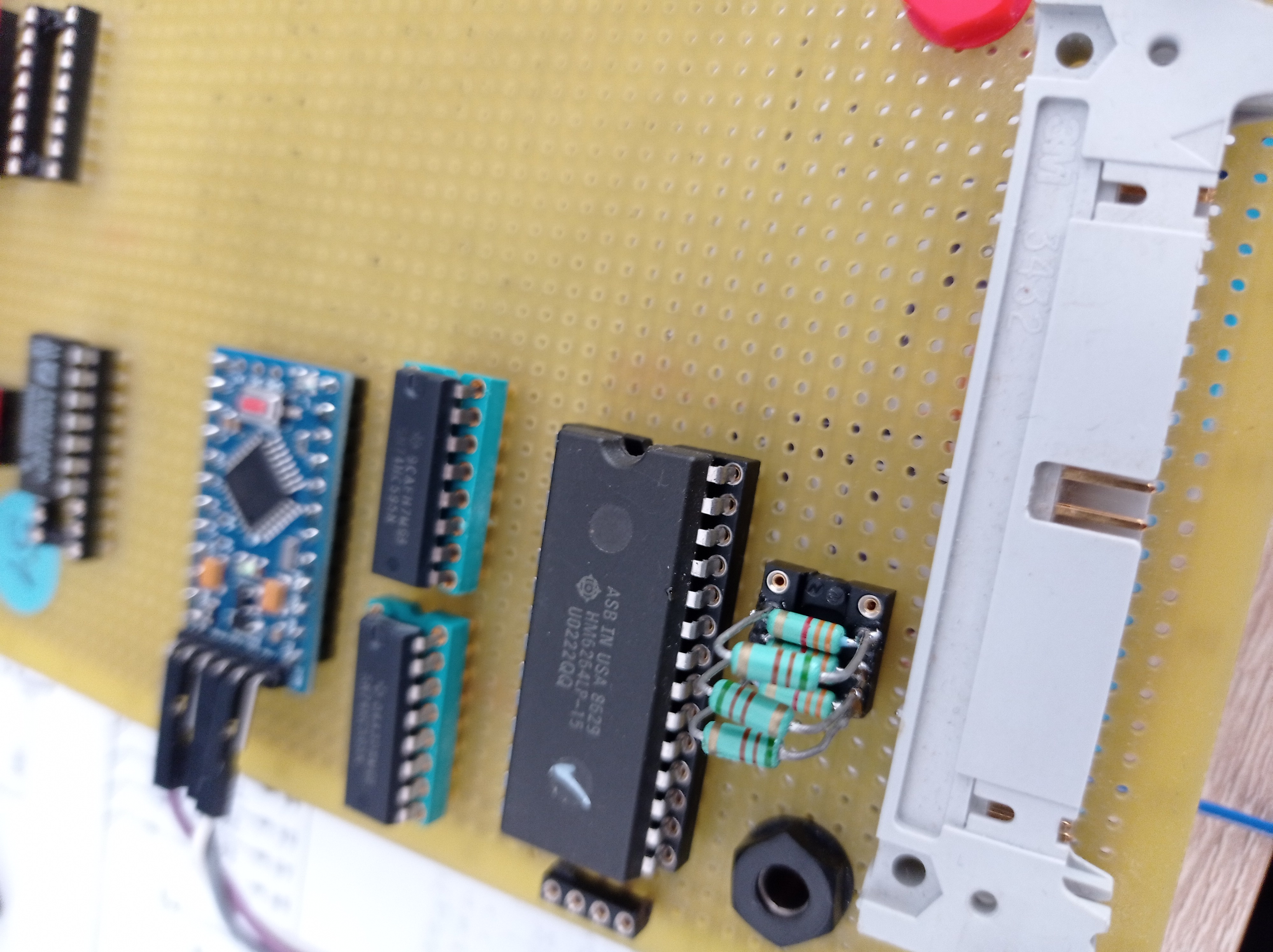
I suspected that the static RAM chip was maybe faulty and in the meantime I was given
another one, which matched way better with the vg5000 vintage-ness:
a magnificent 6264LP-15
(thanks Altomare!)
(I would soon figure out that my WR_ signal logic was wrong…)
So I decided to redo the prototype and solve everything at once.
Fresh restart
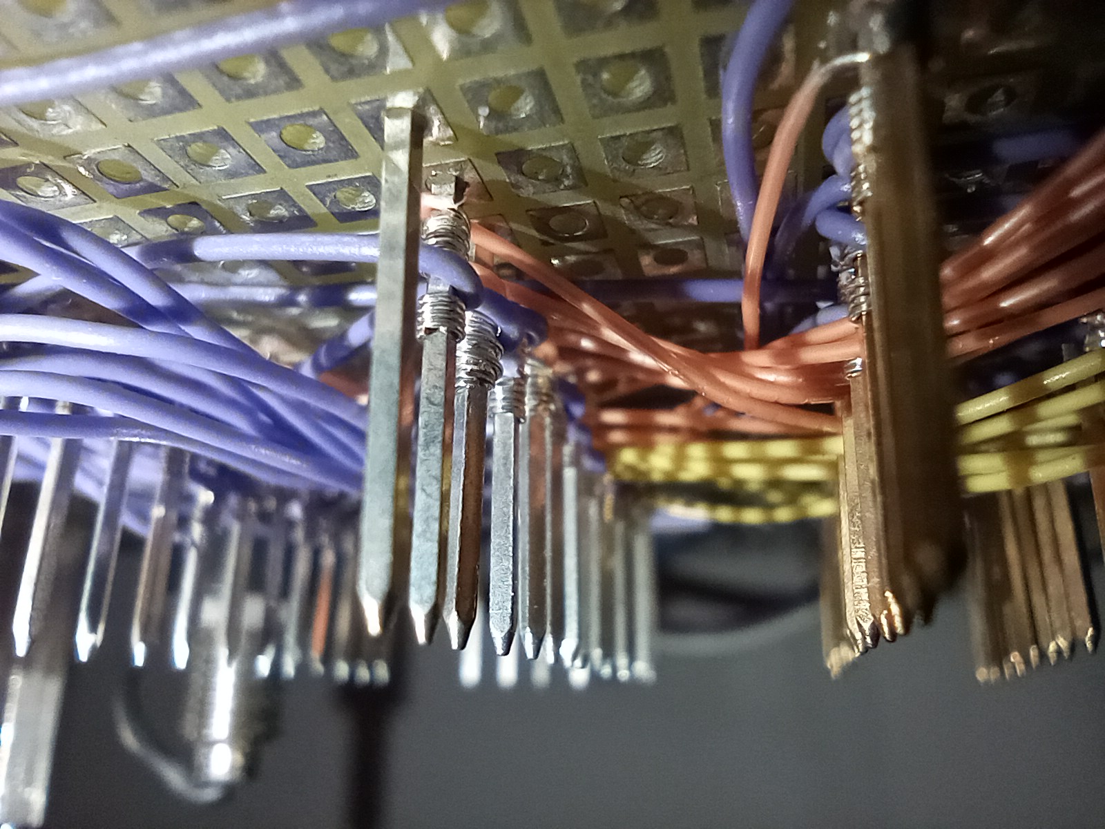
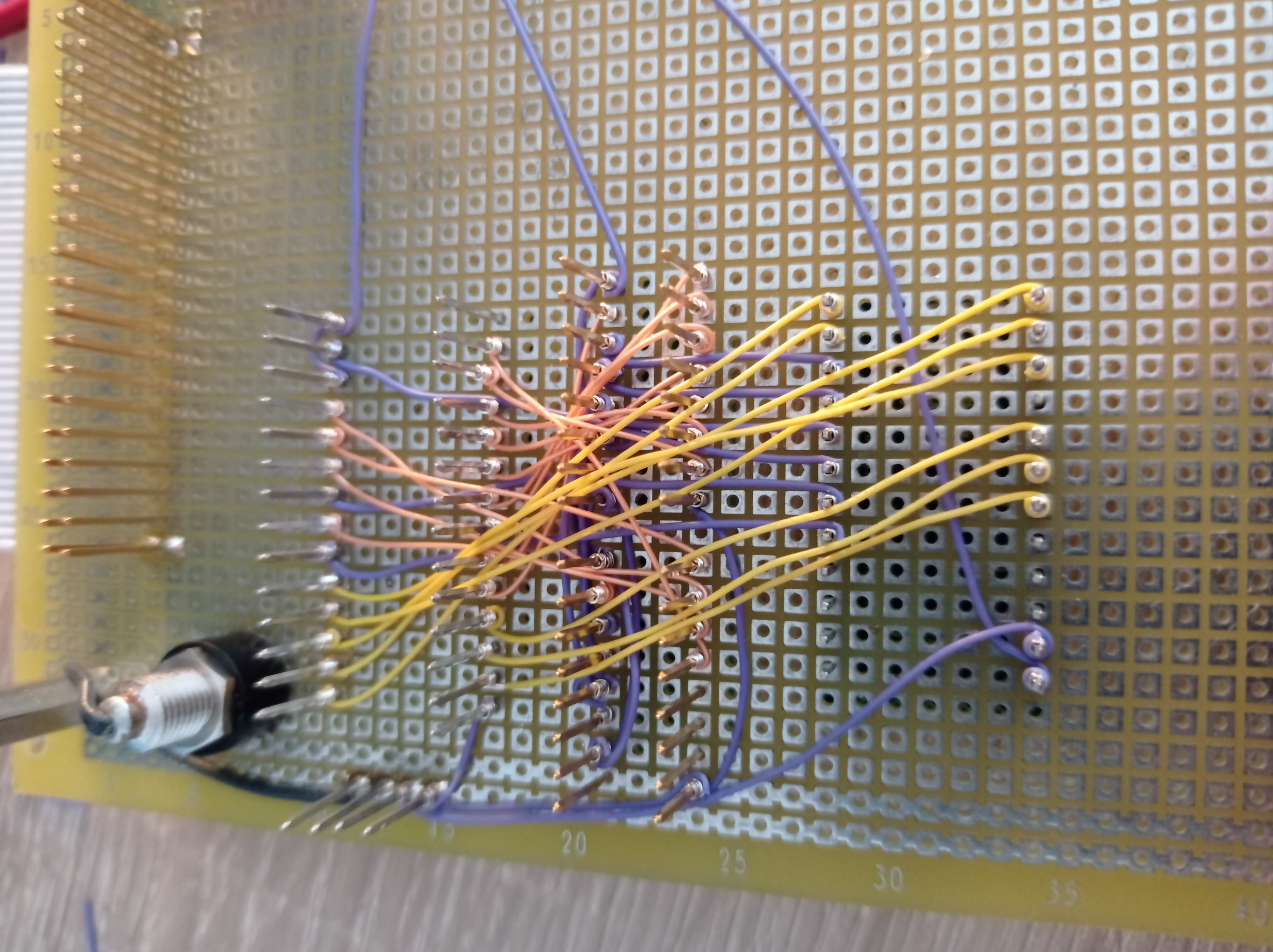
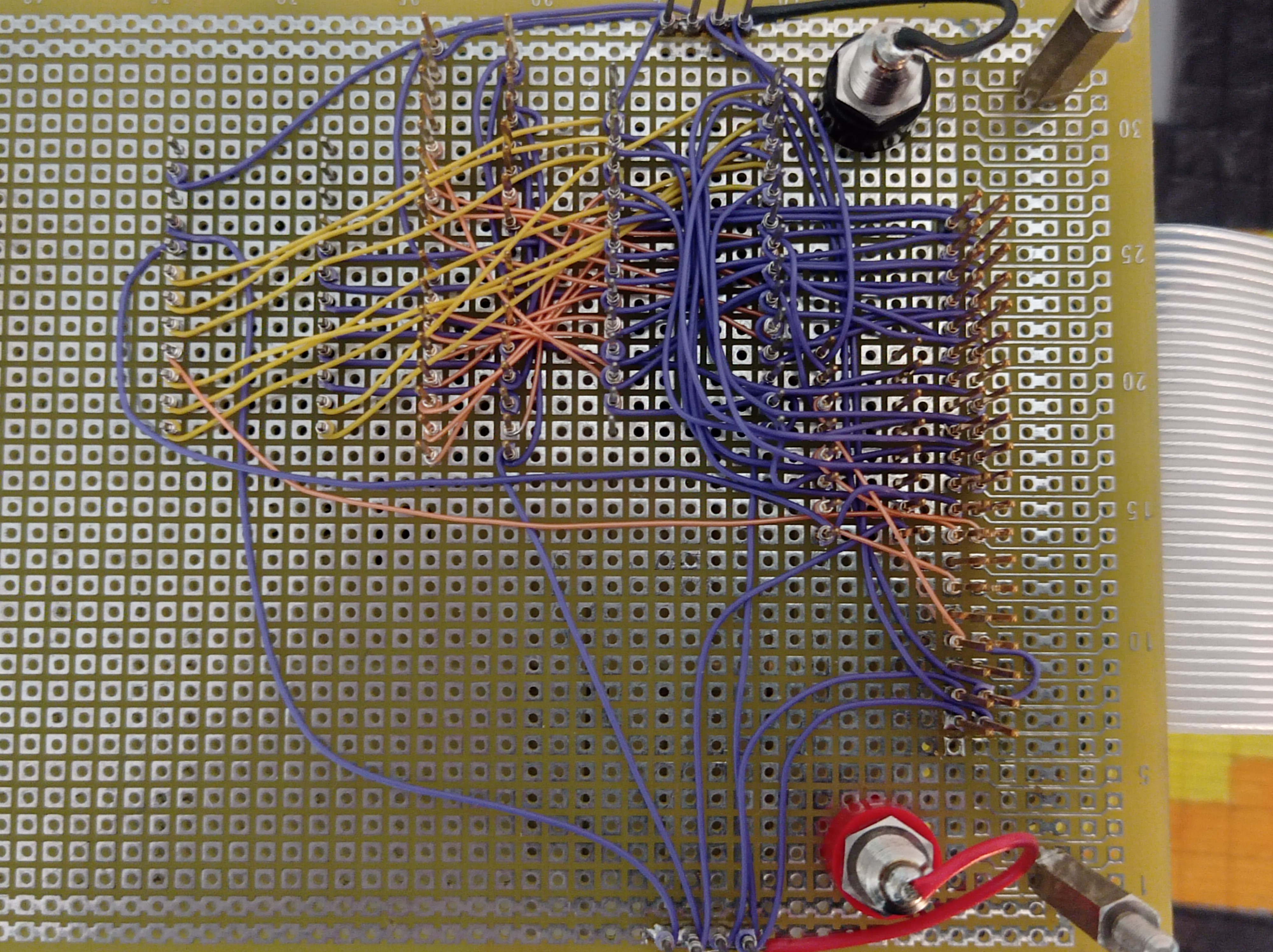
For this second iteration, I used wire-wrap. Wrapping is much faster and reliable… until you want to modify something. But this is fine, since I would never make a mistake *cough*, right ?
 |
 |
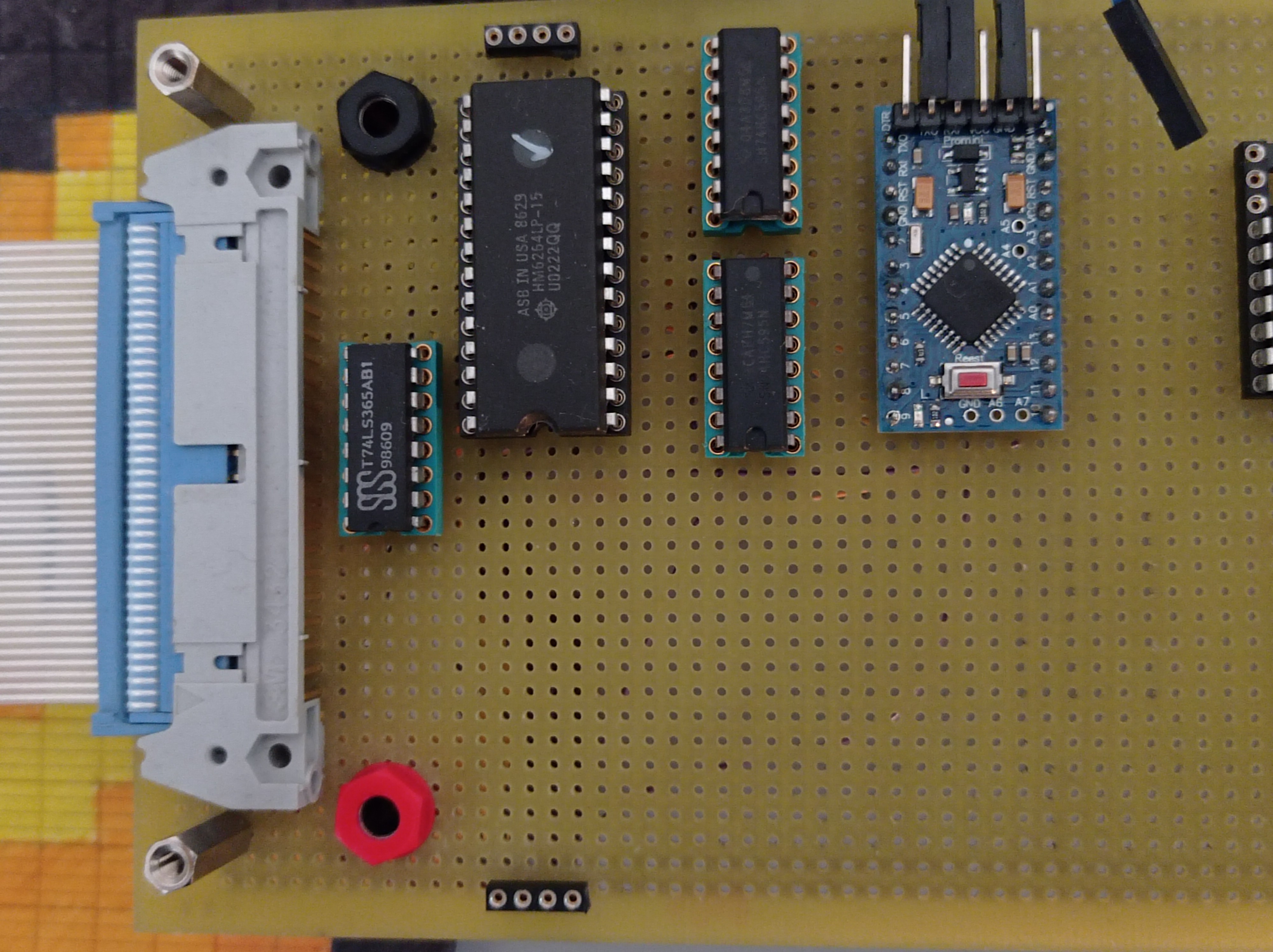
The structure is the same as previously:
- an Arduino is there to serve as a glue between a modern machine and the RAM chip. It bitbangs on data bus, address bus and control signals. A nice property of the AVR chips is their capability of going high-impedance on the GPIO pins. This makes it possible to “hand-over” the buses to the VG-5000.
- two shift registers expand the number of available GPIOs. I used those for the address bus.
- the static RAM chip.
Once this prototype built, I discovered why my previous attempt was unstable. My program sometimes did not handle the WR_ signal high, and garbage was being written.
It resulted that this board reached an excellent reliability level.
The real hardware
Sharing of the control signals
While starting to wrap to the connector, I realized that the Z80 was not going to play nice with the control signals (WR_, RD_, CS_). Indeed, in a traditional microcomputer bus, the signals are typically shared by all the components; this is required to “read” data (the bus is driven by something else than the CPU). But when it comes to the control signals, the Z80 does not go high-impedance…
My first approach was to insert resistors between the main-board and the extension; so that the Arduino could drive with enough current. I tried with 3K resistors, which would result in a few milli-amps: but the residual capacitance on the RAM chip pins, combined with the high frequency did flatten the signals too much.
Tried again with much lower resistor values, it did not work well either. (I would later realize that I had a conflict on the bus; that resistor trick should have worked !).
I reverted to insert a 3-state buffer to decouple the signals. Found a 74365 in the drawer, this is the way.
Debug !
Everything is wired, all tests check… Now I need something to tell me whether the CPU uses the RAM.
I could use the graphic output, but how to make sure that the initialization is done properly ? Let’s generate some sound instead:
org 0

ld b, 8
ld a, b

start:
	xor b
	out (0afh), a

	ld c, 100
loop:	dec c
	jp nz, loop
	jp start
This program was small enough so that I could type it by hand over the serial link.
Ignition, and… nothing !
Multimeter, oscilloscope… I checked and rechecked. Chatted a bit with Altomare, who asked whether I made sure that the onboard ROM chip was disabled.
”- sure ! It is driven by a pull-up that I short…”
I checked and this was connect to … +5V :facepalm:
Fix the wire, ignition, and … nothing ! (but now the signals are clear)
I hunted the bug down to the data bus wiring, with the odd bits being shifted. And:
One small step for mankind, one giant leap for man. Wooh !
Beyond beep
Now that the code seems to run fine, I can create a loader program that takes a binary and throws commands to the Arduino. With this, it becomes reasonable to load much bigger programs.
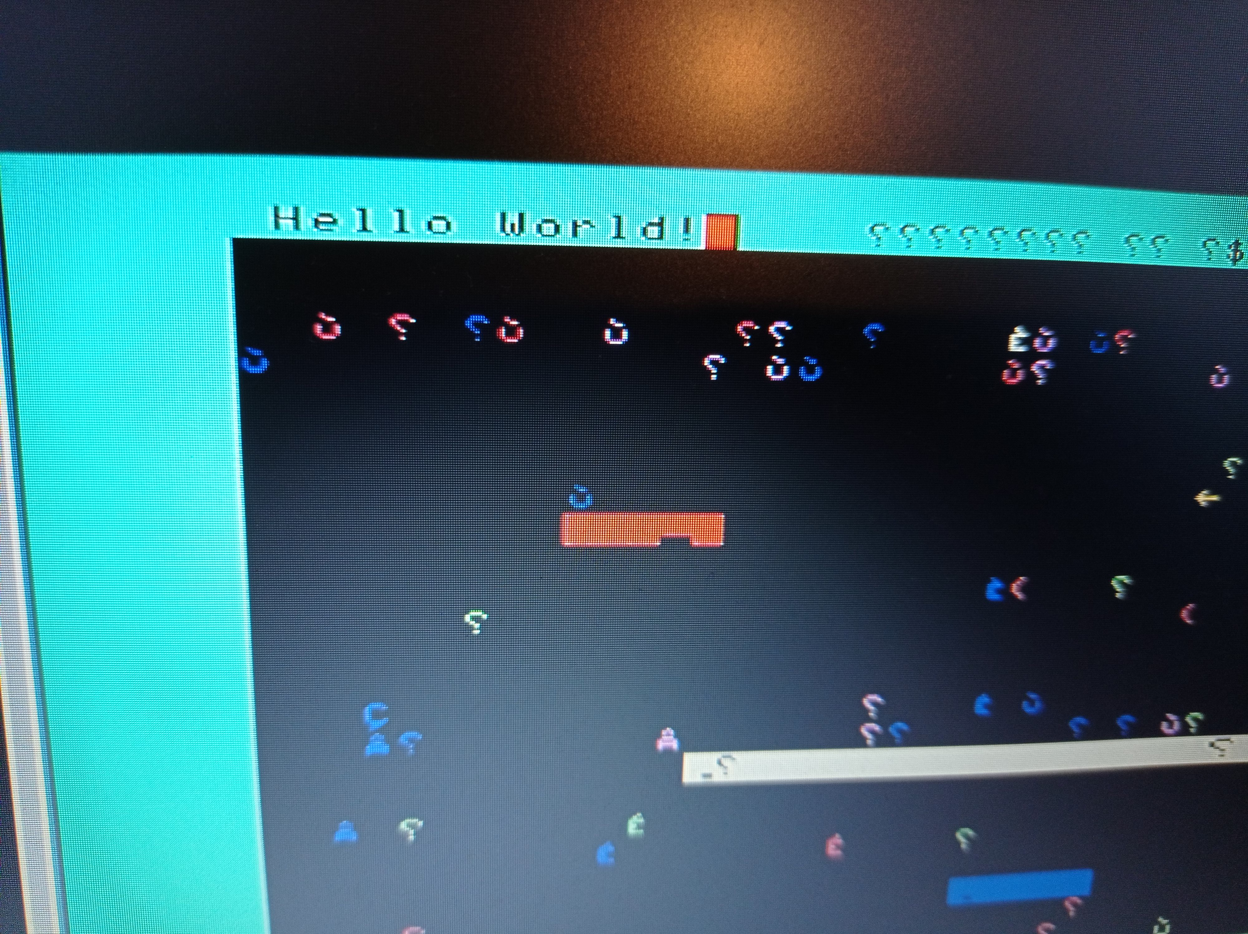
After a few attempts at initializing the graphics chip (remember that there is no more ROM available to help)… greeting from the other side:
 |
 |